<br>
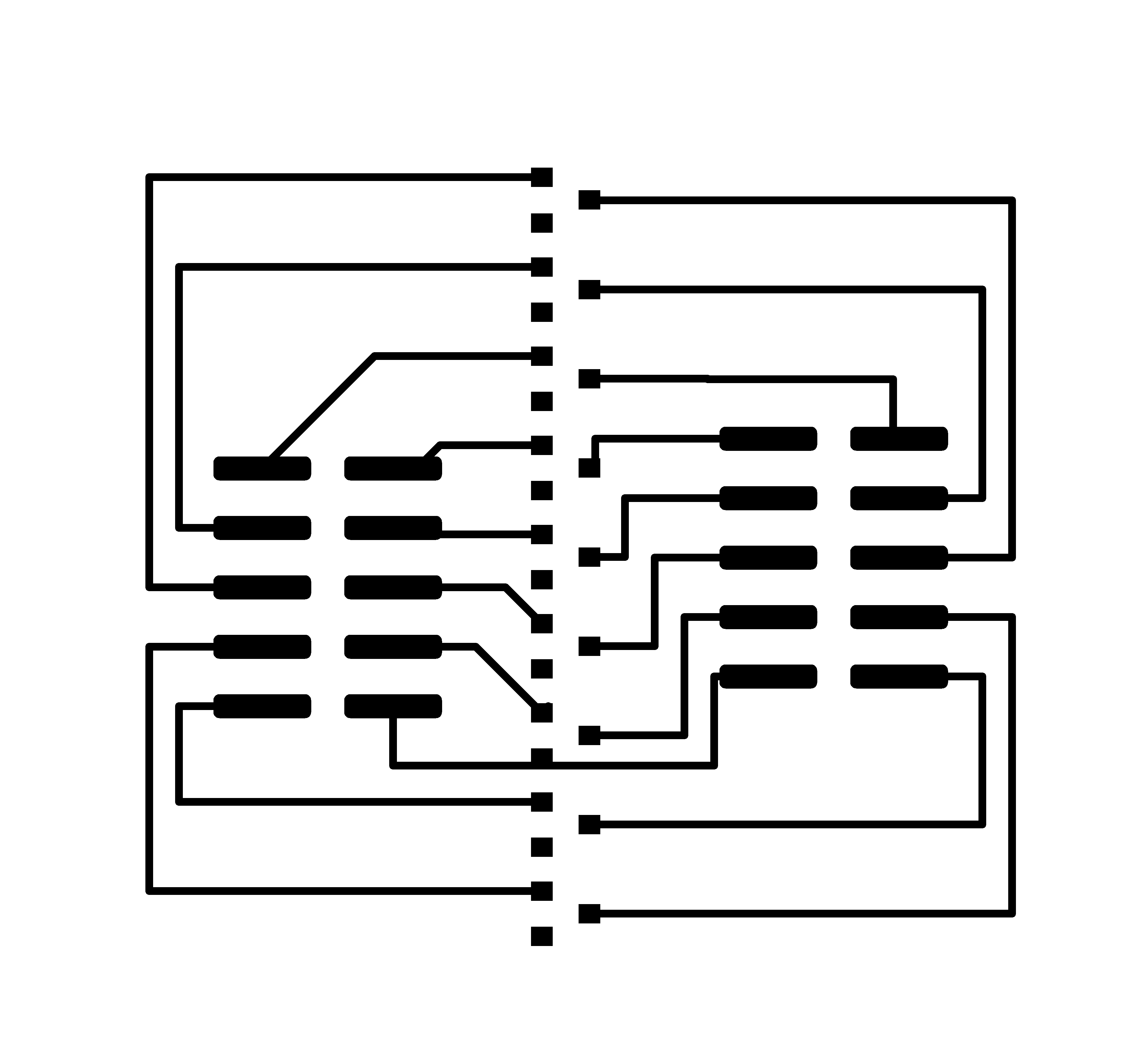
##Nine FETs, surface mount, ribbon cable connector.
###Eagle files and traces.
####Original board, in which wire needs to be added to connect grounds.
These files are at 1000 dpi resolution. When imported into mods, these files give a result that is two times too large.
The dpi in the mods window needs to be set to 2000 dpi to make the board come out at the right scale.
[Eagle board](./FET_Mux/FET_mux.brd)
[Eagle Schematic](./FET_Mux/FET_mux.sch)
[png traces](./FET_Mux/traces.png)
[png outline](./FET_Mux/bottom.png)
####Two-layer board, in which ground connection is made using holes, rivets and soldering to a bottom ground plane.
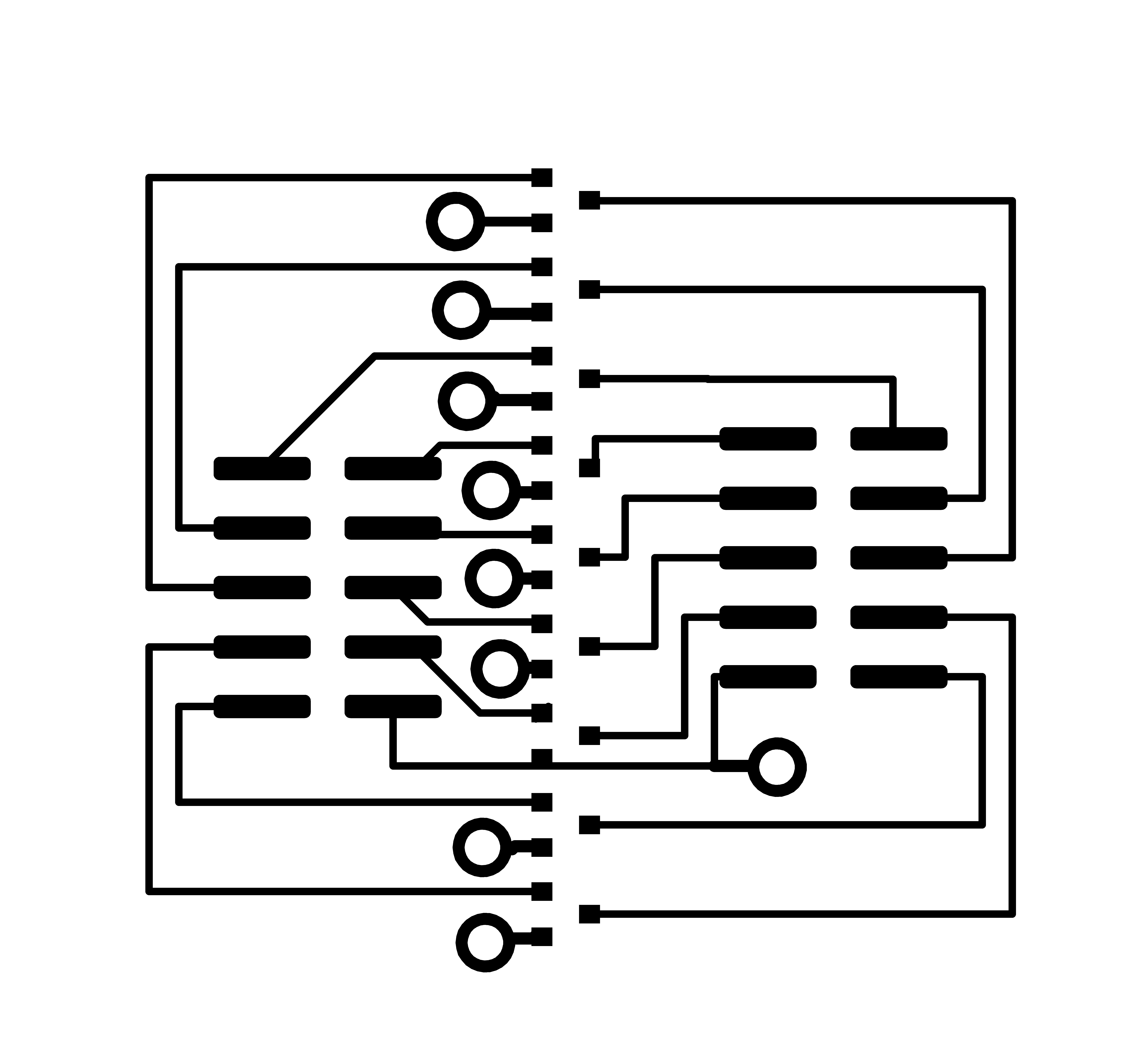
Use a two-layer circuitboard. Note that all the two-layer files are 2000 dpi resolution. When imported into mods, these files give a result that is two times too large.
The dpi in the mods window needs to be set to 4000 dpi to make the board come out at the right scale.
[Eagle board](./FET_Mux/FET_mux_2layer.brd)
[Eagle Schematic](./FET_Mux_/FET_mux_2layer.sch)
[png traces](./FET_Mux/traces_2layer.png) Run with 1/64" endmill. Set at 4000 dpi.
[png holes](./FET_Mux/holes_2layer.png) Run this with 1/32" endmill. Set at 4000 dpi.
[png outline](./FET_Mux/bottom_2layer.png) Run this last with 1/32" endmill. Depth 1.55 mm. Set at 4000 dpi.
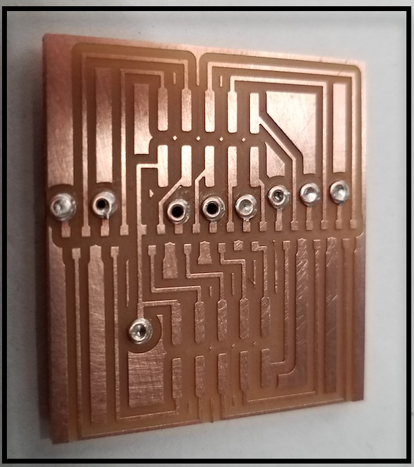
Here's the board, milled, and rivets soldered to ground points.
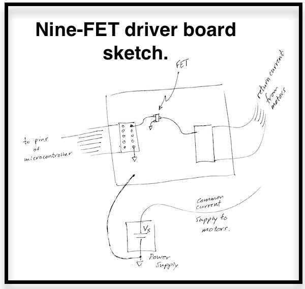
Here's a sketch explaining the layout and routing of current to (up to) nine actuators.