<br>
Return to [Output Devices](./../output.html)
###H-Bridge Module.
<b>Controlling positive and negative current.</b>
- DC motors are driven by supplying a voltage to the leads, and will reverse if the voltage is reversed. The pins
of the Arduino can only supply 40 mA of current, not enough to power most motors.
A motor driver is used when you want to run a motor with more current, for example the current
that might be supplied from an external power supply through the "vin" pin, but still control the motor
with a digital output pin. If you only need to run a motor in one direction, a single [FET](../FET/index.html) will
suffice. However, if you need to be able to run the current (and the mnotor) in both directions, you'll need something like an
[h-bridge](https://en.wikipedia.org/wiki/H_bridge). An h-bridge can be built from components, purchased as a chip, or as a module.
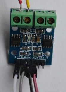
- The h-bridge [module](http://www.mpja.com/H-Bridge-Power-Driver-Dual-Channel-L9110/productinfo/31596+MP) that we have
currently in the bins is pictured below. It can provide 800 mA to each of two motors, and can run them in either direction.
- This board can be used to provide
current to other output devices - for example to speakers. One of these boards can be used to
run a bipolar stepper motor.
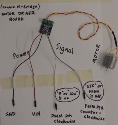
###Tutorial - steps in connecting a motor to the h-bridge module.
1. Attach a power supply to the GND and VCC pins of the module. You may want to use female-female socket wires.
2. Attach motor leads to the output connectors, using a small screwdriver to clamp leads into connectors.
3. Attach two leads to the appropriate signal pins on left or right (eg, B-1A and B-1B). White and gray in the image below.
4. Verify the motor turns clockwise or counterclockwise respectively, when you ground the signal leads. When the voltage on the signal pins is high (3.3V) the motor is off in that direction.
5. Attach the signal leads to microcontroller pins and control direction and speed. When you use analogWrite, remeber that OFF=255 and ON=0. See the code examples.
<p><a href="./Bidirectional_Motor_driver.txt">Here</a> is code to run a motor alternating direction.</p>
<p><a href="./Variable_motor_driver.txt">Here</a> is code to run a motor at a variable speed in one direction.</p>
<p><a href="./Analog_input_Motor_driver.txt">Here</a> is code to run a motor at a variable speed as a function of analog input.</p>
###Running a stepper motor with the h-bridge module.
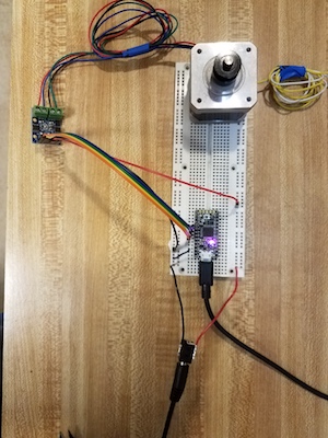
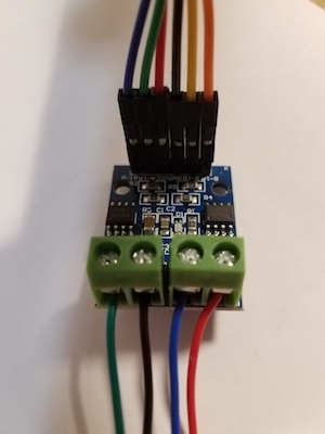
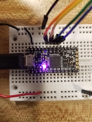
1. Connect the four pins of your microcontroller board to B-1A, B-1B, A-1A, and A-1B pins of the h-bridge module. orange-yellow-green-blue in this picture.<br>
2. Connect your motor leads to the ouput terminals. For the motors you have the pairs for each connector should be black/green and red/blue. If you measure the resistance from one of these pairs to the other, you should get about 30 Ohms. (Check this to make sure you are connecting correctly). The order within each pair does not matter. Reversing the wires just makes the motor step the other direction.<br>
3. Connect power and ground to the h-bridge module. Use the 9V power supply and the barrel connector. In the pictures above ground is black, 9V is red. You cannot power the Itsy bitsy with 9V. (But if you have an UNO clone like the Adafruit Metro328, you can plug the power supply into the connector on the board, and use VIN to supply motor power). <br>
4. Run the program. <br>
###Programs for stepper motors.
[here](./itsy_stepper_library_example.txt) is the example program downloaded from the Arduino IDE examples, for driving a stepper motor. It uses the Stepper library, which should be a part of the Arduino IDE already. If it is not, use the Library Manager under Sketch>Include Library to install it.
[here](./stepper_no_library.txt) is an alternative approach that uses a function in the code rather than a library function. It steps a motor at 100 steps per second, or about 1/2 revolution per second.
###Stepper motor board using the ATSAMD11 microcontroller
[Here is a link to the page](../SAMD11_stepper/index.html) that describes the boards that we have made that incorporate two h-bridge chips on a board ewith a programable ATSAMD11 microcontroller. For use in PS70 Spring 2020.