<br>
Return to [Output Devices](./../output.html)
###stepper motor board with ATSAMD11.
This is a circuitboard designed by Ben Brown here at Harvard, with:
1. An SAMD11 microcontroller with USB connection for programming and providing logic power. Details for programming this micro are [here.](https://roberthart56.github.io/SCFAB/SC_lab/Electronics/Microcontrollers/ATSAMD11/Advanced_circuits_board/index.html)
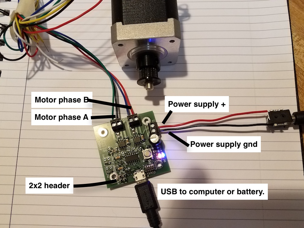
2. Two [h-bridges](https://www.allegromicro.com/~/media/Files/Datasheets/A4950-Datasheet.ashx). These are the chips just above the middle in this picture.
3. Two LEDs for code diagnostics.
4. A 2x2 header that brings out pins 31 and 30 appearing in this picture on the bottom of the board, to the left of the micro-USB connector. These two pins can be used for general purpose digital input/output, and can serve as serial communication pins when you want to communicate between microcontroller boards. More on that on another page!
You can program the SAMD11 to drive the stepper, or other motors. The 2x2 header gives you a convenient way to network this board with other boards, to make a multi-axis machine, for example.
Below is the pinout diagram for this board.
Signal | Microcontroller pin
------------- | -------------
LED1 (blue) | 2
LED2 (red) | 4
Motor A+ | 15
Motor A- | 14
Motor B+ | 8
Motor B- | 5
2x2 hdr, pin 1 | ground
2x2 hdr, pin 2 | 5V in, no direct connection to micro.
2x2 hdr, pin 3 | 30 (TX1)
2x2 hdr, pin 4 | 31 (RX1)
###Code
[simple test code for this board](samd11_stepper_0.txt)
### Schematic and layout
[Link to schematic](schematic.png)
[Link to board layout](hart_stepper_v2-1.png)
###Example of sending serial commands to a motor driver board.
This is an example of using UART to communicate to the motor driver board. Only one of the h-bridges is used in this example.
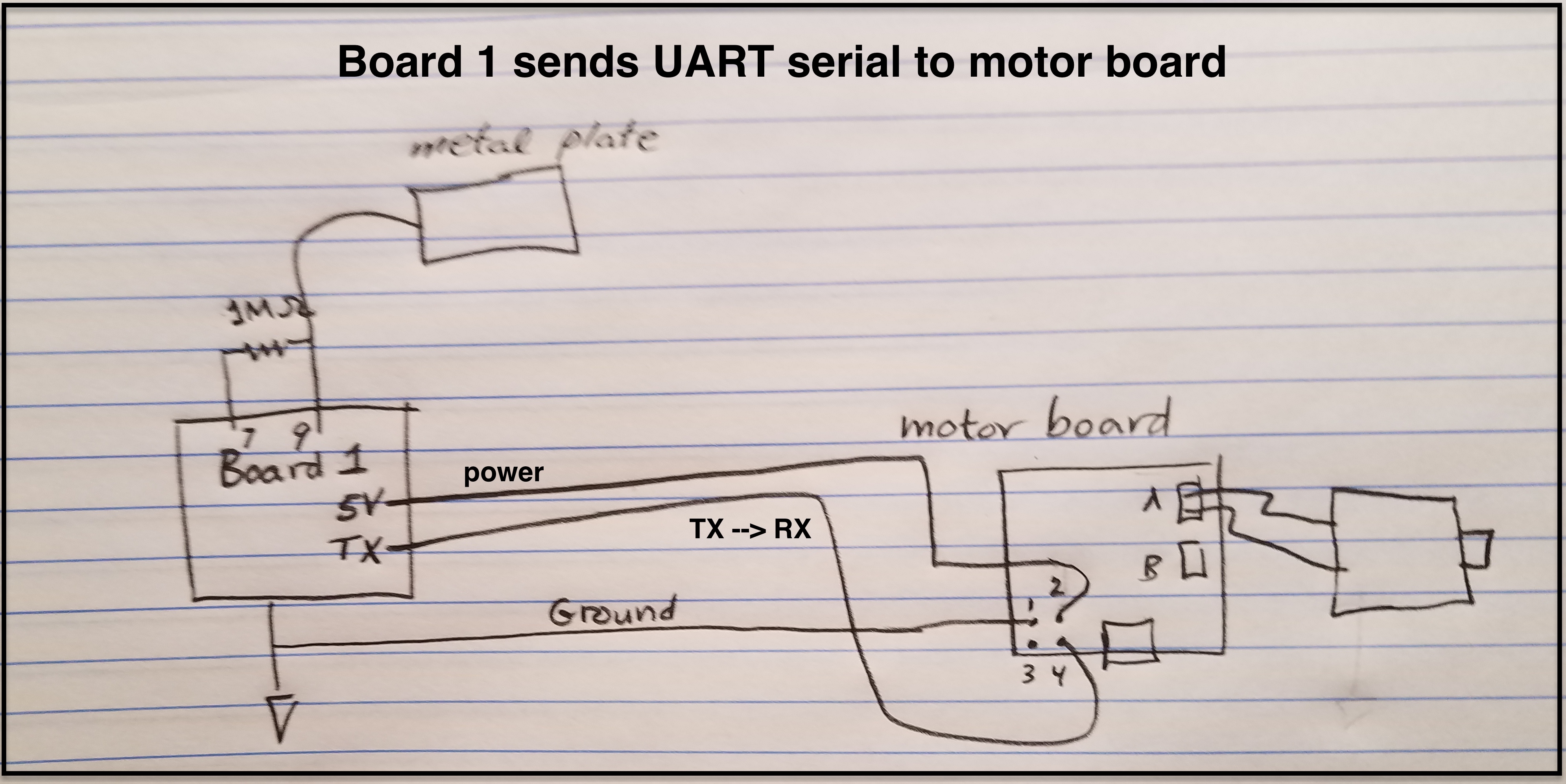
In this example, a microcontroller board (Board 1) is attached to a capacitive sensor. The capacitive signal is converted to a range of 0-255 and sent via UART to the Stepper board. The connection to the stepper board is through the 2x2 header, with:
- ground on pin 1 (connect the grounds of Board 1 and the motor board)
- 5V on pin 2 (This is used to power the board - there is a regulator on the otor board that supplies the 3.3V that the microcontroller needs)
- TX from Board 1 on pin 4 (which is RX for the motor board)
In response to the sent byte (0-255) the motor board drives a DC motor in two directions. In the example, numbers below 128 correspond to one direction and over 128 to the other direction.
[code for motor control board](Capacitance-motor.txt)
[code for capacitive board](capacitance_code.txt)
<video width="300" height="500" controls>
<source src="capac_motor.mp4" type="video/mp4">
</video>
###Example of sending digital levels to control a stepper driver board.
This is an example of using digital levels to command a stepper board to make a single step in one or another direction. Many commercially available stepper drivers are set up to respond in this way.
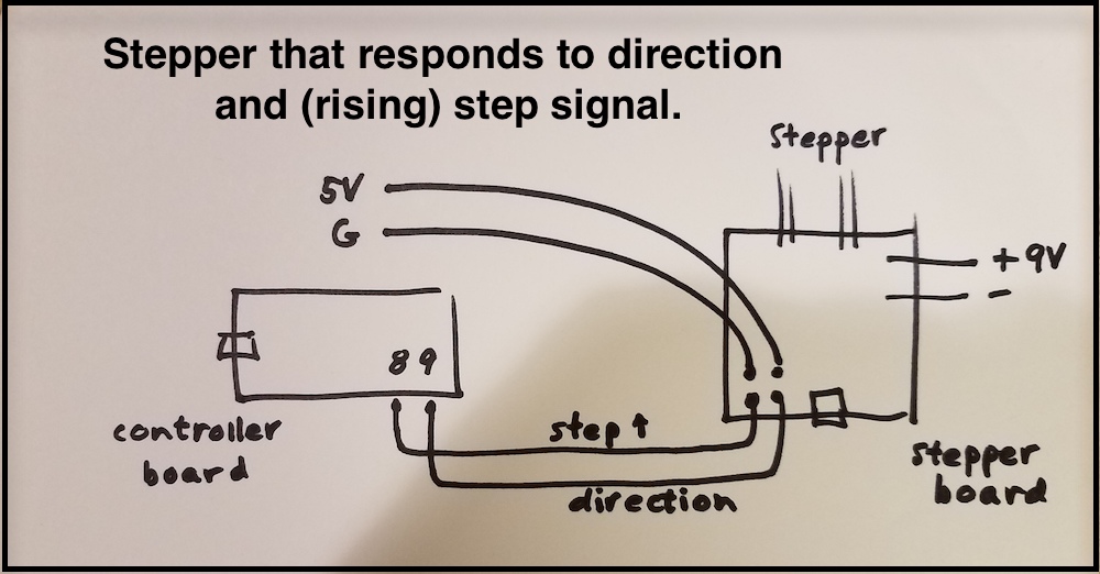
In this example the stepper board microcontroller is powered by 5V and ground from the controller board (on pins 1 and 2 of the 2x2 header). The digital signals come in to pins 3 and 4 of the 2x2 header. The motor is powered from the 9V power supply. The ground of the power supply attaches to the terminal as shown in the sketch. Do not reverse!
[code for control board (sends digital signal).](samd11_stepper_DIO_controller.txt) Control board controls direction with the state of pin 9, and when pin 8 rises from LO to HIGH, the stepper board should make a step. This is the board that would contain code for directing complex moves, or interesting frequency changes. It could be programmed to respond to attached sensors, for instance.
[code for motor driver board](samd11_stepper_DIO.txt) Watches for signal on the "step" input to rise, and then makes a step in one direction or another, depending on the state of the "direction" input signal.
<video width="300" height="500" controls>
<source src="stepper_DIO.mp4" type="video/mp4">
</video>
###Example of a networked machine using this driver
[Page from PS70 machine "week"](../../PS70_machine/index_rev1.html)