<br>
Return to [Output Devices](./../output.html)
###How to use a FET (Field Effect Transistor) to switch a current in one direction.
####How a FET works and how to hook one up to drive a motor or other load.
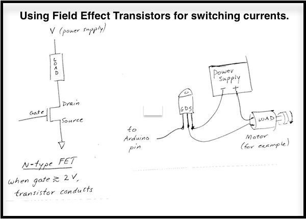
A transistor is a device in which a small current delivered to one terminal (gate or base) controls a larger current through the other two leads. This property makes transistors useful as amplifiers. We will use field effect transistors (as opposed to [bipolar juncton transistors](../BJT/index.html)) - and we will usually use them in a non-subtle way - either fully on or fully off. Use a FET when you need to control a current larger than ~20 mA (0.020 Amperes) with a microcontroller. The current only goes in the direction from the drain to the source (you can reason out why this seems backwards but actually makes sense.) If you need to control current in two directions, use an [h-bridge](../h_bridge/index.html).
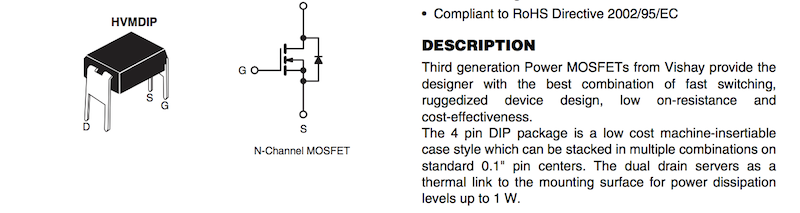
- The FET that we have in stock, IRLD024, can conduct up to 2.5 Amps, and can operate with drain voltage up to 60V. This current and voltager is enough for most things that you will need to drive. Check the [datasheet](http://www.vishay.com/docs/91308/sihld24.pdf) for details. The first part of the datasheet for this part is shown below. Use the labels on the picture of the device to help you orient and
connect the FET on your breadboard.
It requires almost no current from the pin attached to the gate to control a large current flowing from
drain to source of the FET.
- The load can be turned off and on just by switching the pin at the gate between LOW and HIGH. The load, for instance
a motor, can usually be controlled betwen full 'on' and full 'off' by using pulse width modulation (PWM). In the Arduino
code, this is done with the function analogWrite(). See the Arduino reference for details.
- A bigger FET, that conducts up to 55 amperes, is available as well. Its designation is P55NF06.
Its datasheet is
[here.](https://www.st.com/content/ccc/resource/technical/document/datasheet/49/c5/a8/71/93/60/4f/86/CD00002690.pdf/files/CD00002690.pdf/jcr:content/translations/en.CD00002690.pdf)
- The FETs we have shown here are all n-type MOSFETs (Metal oxide - silicon Field Effect Transistor). They also come in p-type, which turn on when the gate is at a lower
voltage than the source.
###Tutorial
####Take these steps to use an FET with microcontroller.
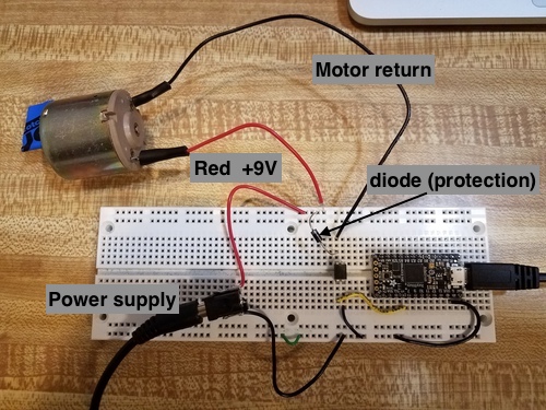
1. Attach your power supply to one of the rails of the breadboard. You may use an external supply, as shown above, or the 5V or 3.3V supply from the microcontroller (limits your current to ~100 mA).
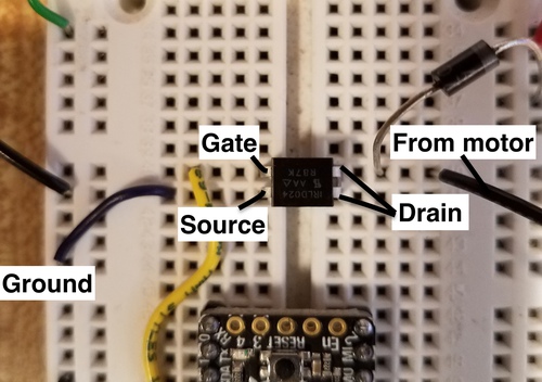
2. Place the FET on the circuitboard. Locate the three terminals. The Drain on the IRLD024 is connected to two pins. Connect the drain to the positive side of the power supply.
3. Connect the source pin to ground.
4. Connect your motor, one lead to the power supply positive, and one to the transistor Drain. Add a diode, as shown below, to protect the FET from transient voltage spikes as the motor turns off and on.
5. Connect a signal lead to the Gate of the transistor. (yellow wire in this picture.) When the gate voltage is above about 2 Volts relative to ground, the transistor counducts current. When the gate voltage is lower than that, the transistor blocks the flow of current, and can withstand a large power supply voltage. Try this by moving the signal lead between ground and a higher voltage. The motor should switch off and on.
6. Now you can connect the signal lead to a microcontroller pin and write code to turn the motor off and on (using digitalWrite) or to control its speed (using analogWrite for PWM).
####Arduino Code
- [Driving with digital Write.](./digitalWrite_FET.txt)
- [Driving with analog Write.](./analogWrite_FET.txt)
####Flyback diode for inductive loads.
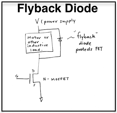
- When driving a motor or solenoid, or other inductive load (load that creates a magnetic field) it is necessary
to add a diode across the motor leads, as pictured above, in order to protect the FET from high transient voltages that
occur as the current is being switched off. Notice that the diode is placed so that it does not conduct when the load
is energized.