<br>
Return to [Output Devices](./../output.html)
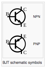
###NPN BJP (bipolar junction transistor)
[wikipedia link to BJT](https://en.wikipedia.org/wiki/Bipolar_junction_transistor)
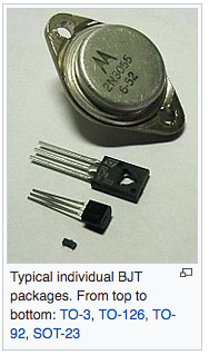
####A transistor is useful when you need to control a current larger than ~40 mA (0.040 Amperes) with a microcontroller.
The NPN transistors that we have can conduct up to 1 Ampere. Larger capacities are available.
For larger currents, we often use [FETs](../FET/index.html) instead.
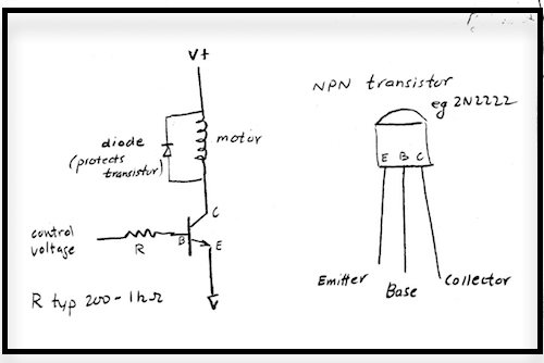
- The signal voltage is attached through a resistor to the base of the transistor. When the signal voltage is zero, there is no current flowing into the
transistor base, and the transistor does not conduct. As the signal voltage rises, a small base current turns on a much larger ( ~100 X )
current (up to 1 ampere in this example) flowing from collector to emitter of the transistor.
- When driving a motor or solenoid, or other inductive load (load that creates a magnetic field) it is necessary
to add a diode across the motor leads, as pictured above, in order to protect the FET from high transient voltages that
occur as the current is being switched off. Notice that the diode is placed so that it does not conduct when the load
is energized.
- The load can be turned off and on just by switching the pin at the gate between LOW and HIGH. The load, for instance
a motor, can usually be controlled betwen full 'on' and full 'off' by using pulse width modulation (PWM). In the Arduino
code, this is done with the function analogWrite(). See the Arduino reference for details.
____
____
####Here is one way to make a more permanent circuit to drive a motor.
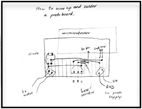
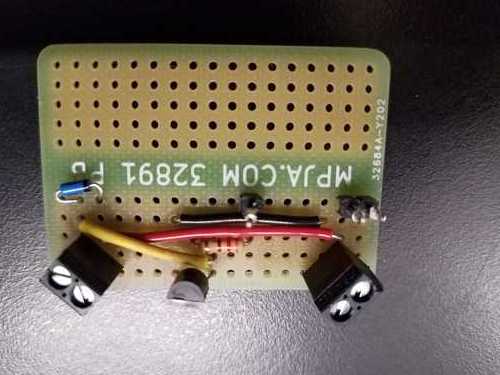
Sketch on the left, and soldered-up protoboard on the right. As in the breadboards, the columns of holes are connected
electrically on the underneath side of the board.
___
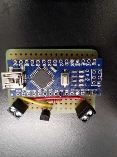
Now with Arduino Nano attached.