<br>
[Return to Networking menu](../index.html)
###Introduction to UART.
The universal asynchronous receiver-transmitter (UART) takes bytes of data and transmits the individual bits in a sequential fashion. (Direct quote from the [wikipedia page](https://en.wikipedia.org/wiki/Universal_asynchronous_receiver-transmitter)). A byte is eight bits, corresponding to numbers between 0 and 255 in base ten.
More resources:
- [ASCII table](https://www.sciencebuddies.org/science-fair-projects/references/ascii-table#asciitable) for interpreting bytes as characters.
- [UART tutorial](https://learn.sparkfun.com/tutorials/serial-communication/all)
- [SPI tutorial](https://learn.sparkfun.com/tutorials/serial-peripheral-interface-spi)
- [I2C tutorial](https://learn.sparkfun.com/tutorials/i2c)
###Example using two boards.
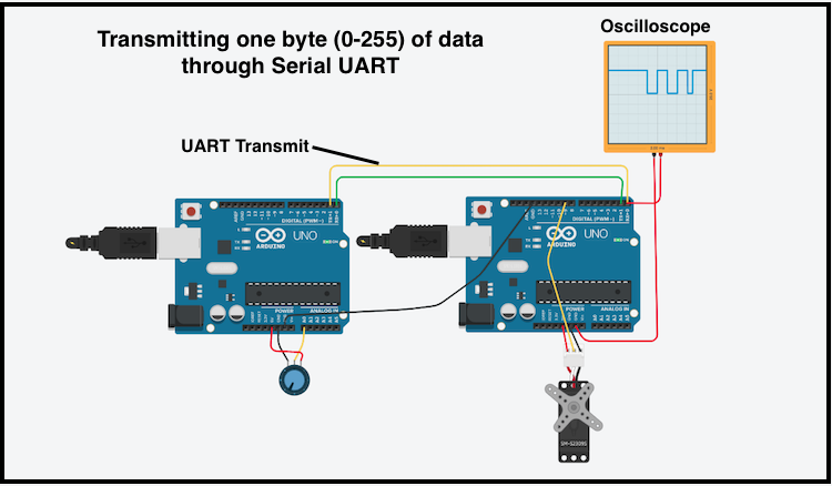
[Link to tinkercad model for simple UART](https://www.tinkercad.com/things/2C1xWqjhOfL-serial-comm/editel?sharecode=-i_64yYC0v7TeIwGWku7Rxm_X6fyBYPSOyJV2EBF1CI). This link allows the user to see the serial signals in a virtual oscilloscope.
Below is a simple example that of two boards communicating by UART serial protocol (only one way in this example.) The board on the left writes a byte based on a voltage read from a potentiometer. The two boards must share ground. They must both be powered, and can share a power line. The board on the right receives the byte and converts it to an angle command for the servo.
In the current example, we have not added much capability beyond the [simple servo driver](https://nathanmelenbrink.github.io/ps70/08_output/servo.html), and it may not be obvious that this accomplishes anything. It can be extended to do a great deal:
- You can extend this example to let communication happen both ways. Just connect RX of the left one to TX of the right one, and progam them to have a conversation.
- You can add many devices in a network using a single UART bus, and give them addresses.
- It allows you to make your project more modular.
- It is now ~ one short step to adding radio or internet communication between boards.
###Schematic of this example.
[Link to Tinkercad Model](https://www.tinkercad.com/things/kk1prSXoe8S-ingenious-kieran/editel?sharecode=6MK0TBx0VYrYbc0tEjQxF28xK8NKFxjKRAYrD2JlKU0)
[code](./usart_tx.txt) for the transmitting board.
[code](./usart_ESP32_rx.txt) for the receiving board, written for the ESP32 Huzzah board. While using the UART (referred to as "Serial1") on the board, you can independently use the serial connected to the USB (called "Serial"), as done in this code. This is very useful for troubleshooting and diagnosing as you write code. Just connect a computer and use the Arduino Serial monitor.
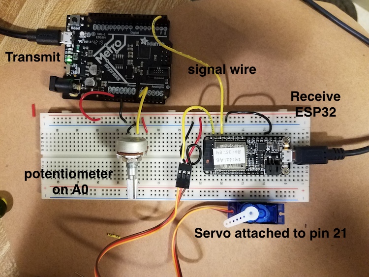
###Details and connections.
Metro M0 board on upper left, powered through computer USB, reads potentiometer voltage and sends one byte through the transmit (tx) line. ESP32 board on right receives a byte (0-255) converts it to an angle (0-180 degrees) and moves the servo. The ground pins of the two boards nust be connected for this to work!
###Video.
A video of two different boards, doing the same thing, with essentially the same codes as linked above.
<video width="1000" height="541" controls>
<source src="uart_demo.mp4" type="video/mp4">
</video>