<br>
#Electronics basics.
##A few of the most common components and their symbols.
[Resistor color code link](http://www.resistorguide.com/resistor-color-code/)
---
##Voltage
###Current flows through a circuit;
###Voltage is the energy that the charges have at a particular place in the circuit.
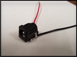
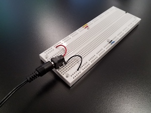
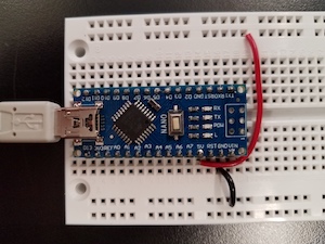
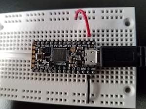
- The pictures above show two ways to supply voltage to a protoboard circuit. In the left two pictures, using
an external power supply (any voltage) through a barrel connector to which leads have been soldered. On the right, using the Arduino Nano board, which provides
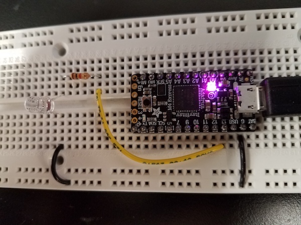
five volts. Lower left, using the ItsyBitsy M4 in the same way. It is powered by 3.3 V and can be destroyed by 5 V. Beware!
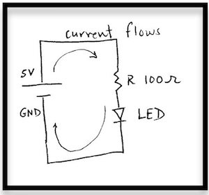
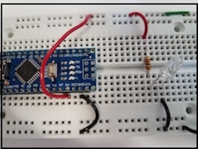
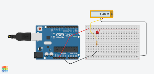
- On the left a schematic and on the right the actual circuit. Then, a Tinkercad simulation. [Link to Tinkercad design. ](https://www.tinkercad.com/things/jhqvmlJavmN-ledarduino/editel?sharecode=aTIV-EgU_saw91k_jmfzS_4LVqcaU6PPDRTf071NweE)The arduino pins at 3.3V (or 5V) and GND act as the "battery".
[Tutorial on breadboard circuits.](https://learn.sparkfun.com/tutorials/how-to-use-a-breadboard)
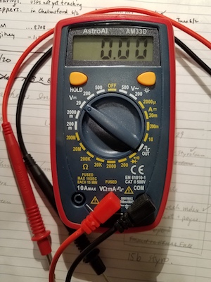
Using a multimeter to measure voltage (with respect to ground) at points in a circuit.
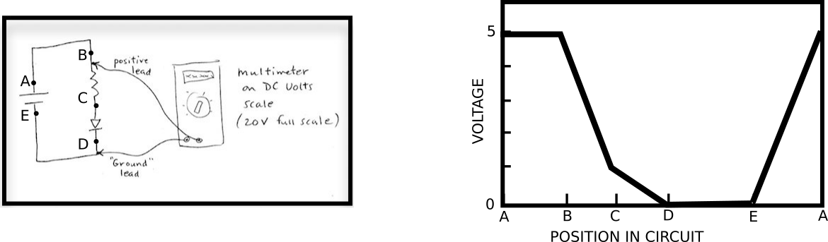
- The multimeter is used in the DC voltage mode to measure the voltage around the circuit. The voltage reference
or "ground" is chosen to be the negative terminal of the battery. A graph of these voltages is shown on the right procceding
around the circuit from A through E and back through the battery to A again.
---
##Current
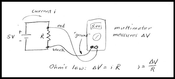
- Ohm's law applies to resistors. Use Ohm's law to calculate the current flowing through
a resistor.
---
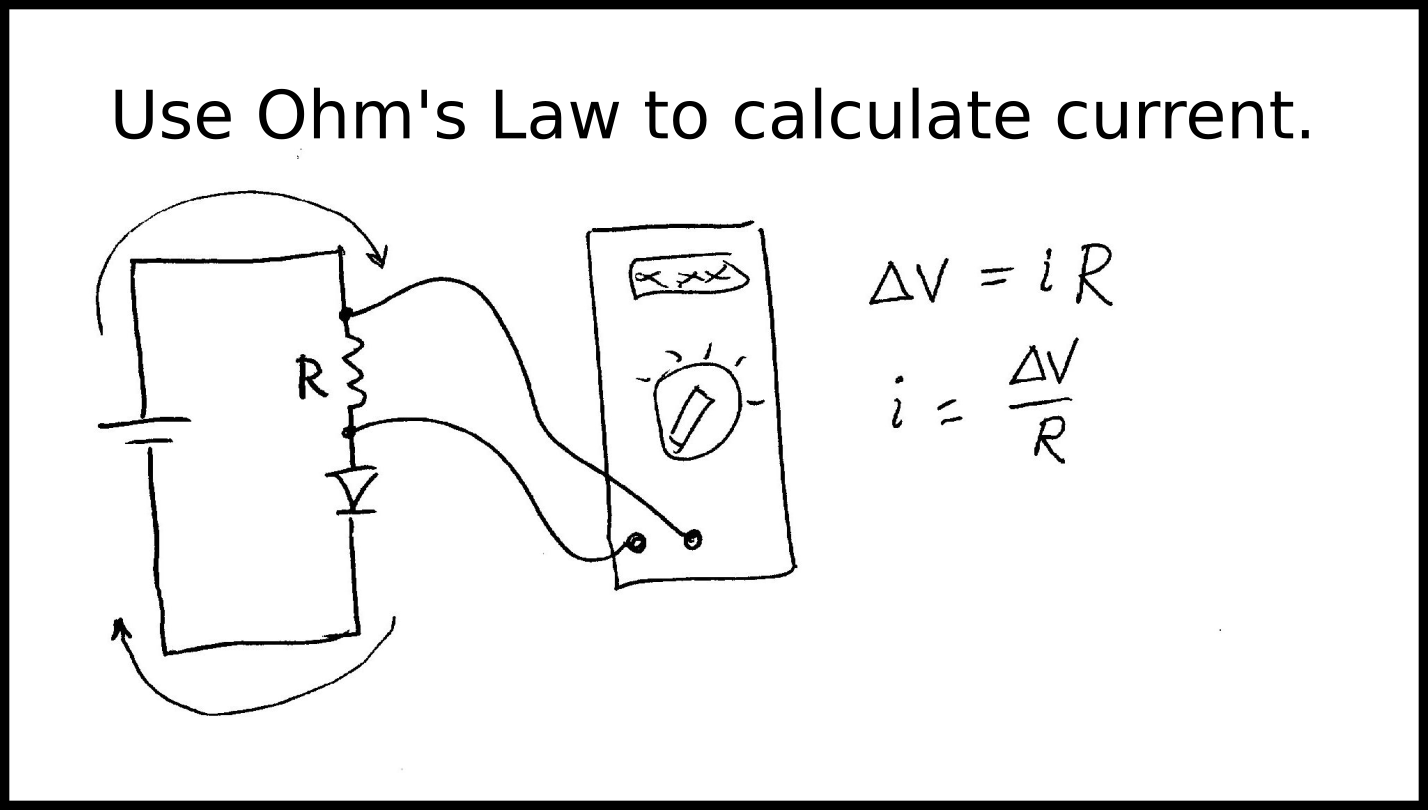
- An LED does not have the simple relation between voltage and current that a resistor does (Ohm's law
does not work for diodes). To learn what current is flowing through the LED, you need to use the fact that the current flowing through the resistor is
the same as that flowing through the LED. Then measure the voltage across the resistor and use Ohm's Law to find the current.
Build the circuit shown above, and calculate the current flowing through the circuit.
---
##The Blink Circuit with a 3.3 V Adafruit M4 board (ItsyBitsy.)
---
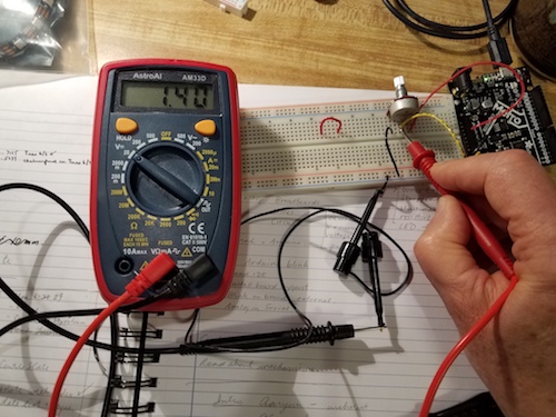
##Arduino as a voltmeter.
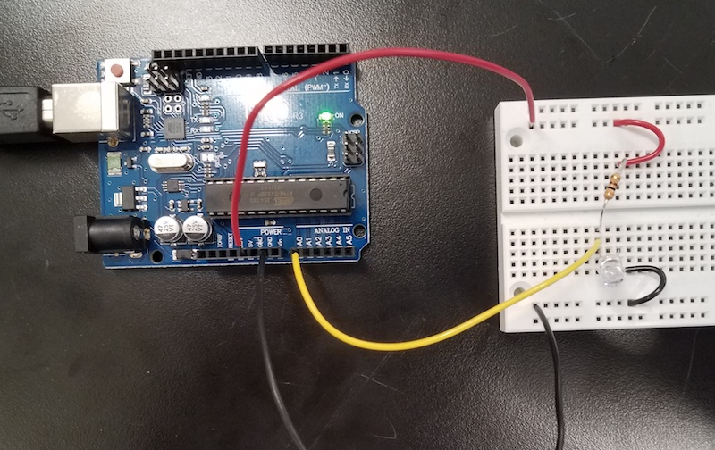
Use the Arduino as a voltmeter. In the picture above, the A0 pin of the Arduino is used with the yellow lead, to measure
voltage, using analogRead. Use the program in Arduino IDE, File>Examples>Basic>AnalogReadSerial. Open the serial monitor
or the serial plotter in the Arduino IDE. Probe the circuit to measure voltages relative to ground.
---
##Power
Power is the energy per unit time that is used or dissipated by a circuit element. It is calculated as:
<b> P = I x V </b>
With current in Amperes and V in volts, Power has units of Joules/second or Watts.
Alternatively, Ohm's Law can be used to give:
<b>P=I<sup>2</sup>R or P=V<sup>2</sup>/R </b>
---
##Voltage Divider
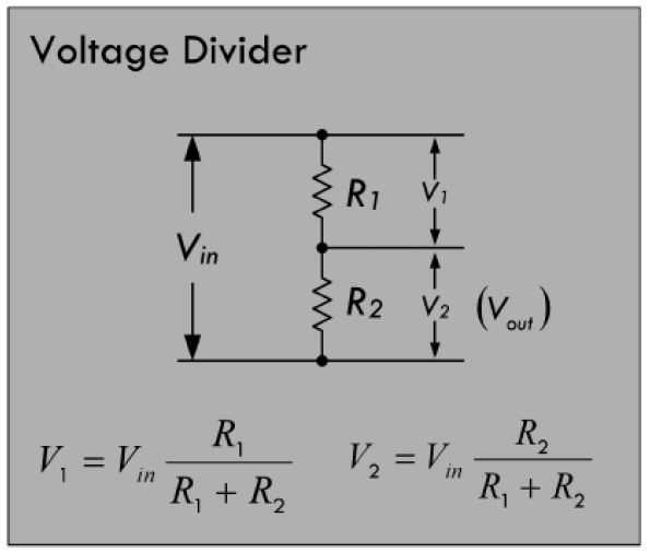
- Voltage divider. Here is a voltage divider, which forms the basis for many sensors. Build this circuit
with resistors, and measure voltages. Does it make sense to you?
---
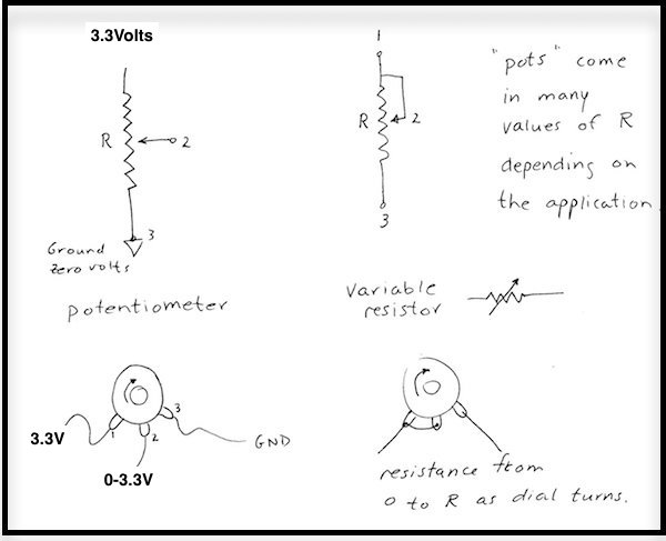
- Potentiometers. A potentiometer is a voltage divider with a movable contact. It can be used to provide a variable voltage, or act
as a variable resistance.
---
##I-V Curves

Ohm's Law describes a linear relationship between current and voltage: &Delta V = iR. It holds for a resistor, conducting
current within its normal operating range. for other devices, such as diodes (for example, LEDs) the relation is not linear. For
these devices, we need to use the Current-voltage curve (I-V) to model the behavior in a circuit.
[Current-voltage curves](https://en.wikipedia.org/wiki/Current%E2%80%93voltage_characteristic)
[Load lines](https://en.wikipedia.org/wiki/Load_line_(electronics)
##Capacitors, time-varying voltage, Oscilloscope
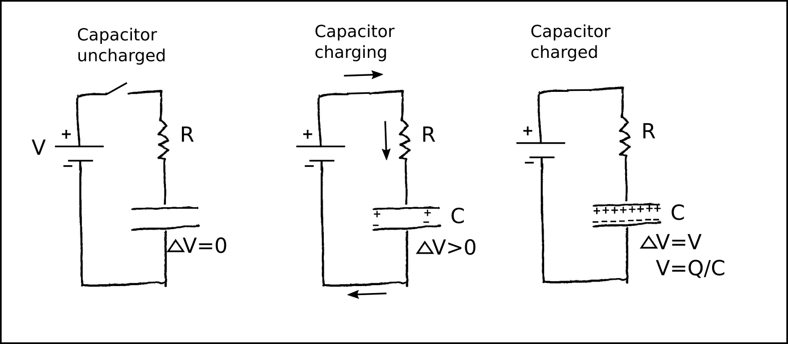
- A capacitor stores energy within its internal electric fields. As current flows through the capacitor, the voltage across its teminals
increases as V = (1/C)*Q where C is the capacitance in Farads and Q is the total charge that has passed through the capacitor.
- [Applet by Falstad demonstrating capacitor charging.](https://www.falstad.com/circuit/e-cap.html)
- Oscilloscope.
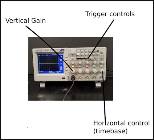
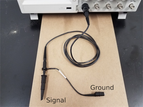
- Use Oscilloscope to measure voltage of Arduino as it blinks.
- Use the Oscilloscope to monitor capacitor voltage as it charges.
##Other resources for electronics.
- <b>[Getting started with Arduino](../Arduino/index.html)</b>
- <b>[Intro by Lara Tomholt](Lara_Tomholt_Workshop.pdf)</b>
- <b>[More introductory material from a HTMAA recitation.](https://tourlomousis.pages.cba.mit.edu/fabclass-recitation-electronics/basic_concepts/index.html)</b>